Corrosion – Chapter 2. – The behaviour of stainless steel bridge against corrosion

The behaviour of stainless steel bridge against corrosion 


About 40% of bridges in the United States were built from steel, in Japan alone there are more than 50,000 steel railway bridges. Corrosion can lead to the progressive weakening of steel bridges’ structures, the reduction of their static capacity and increase of the dynamic vulnerability of the bridges [1]. Different types of steel are used for bridge construction, such as carbon steels, high strength steels and from the 1960s also weathering steels.  The main damage is the appearance of rust, which can be eliminated not only by rust removal, but prevented altogether by building bridges  from stainless steel. 


Duplex stainless steels are increasingly used for bridges due to their good corrosion resistance and easy maintenance. Mameng at al [2] checked several bridges in their research to investigate their condition in the installation environment. 


Two bridges over rivers and one footbridge near the seaside was examined. In one case corrosion patches (rust) appeared on the bottom of the bridges, but it was suspected that the beam had been rested on steel trestles at some point during their production, transportation or installation. In another case, pitting was observed also on the bottom of the bridge. This bridge spans a river near the sea. The pitting was caused by evaporation of salt water, where this  steel surface was not exposed to washing by the rain. In both cases it was found that these surface defects do not affect the life of the bridge.


  In the footbridge, discolouration was found along the welds, but these were not corrosion patches. 


Figure 1. Footbridge of Sölvesborg (Sweden) [3] Figure 2. Galvanic corrosion on the footbridge [3]


Galvanic corrosion can be found on cable fittings of the footbridge which was caused by the potential difference between the ‘love locks’ and the base material, but it did not affect the lifetime of the bridge. No special corrosion protection was applied to these bridges, this was left to  the innate corrosion resistance of the steel. However, there are cases when the aim is to improve the protection of the material against corrosion; weather is by far not the only corrosive medium, for example acids, alkalis and drug substances used in the chemical, pharmaceutical or food industries can also be highly corrosive. 


Many types of research investigate the corrosion resistance of nitrided steel to improve the protection of the surface which will be presented in Chapter 3. 


References:

[1] Shuaicheng Guo, Ruizhe Si, Qingli Dai*, Zhanping You, Yunxiang Ma, Jiaqing Wang: A critical review of corrosion development and rust removal techniques on the structural/environmental performance of corroded steel bridges. Journal of Cleaner Production (2019) 233. 126-146

[2] S. H. Mameng, A. Backhouse, J. McCray, G. Gedge: Experience of duplex stainless steels as structural materials for bridges. IOP Conf. Series: Materials Science and Engineering 419 (2018) 012018.

[3] S. H. Mameng, A. Backhouse, G. Gedge: Experience of duplex stainless steels as structural materials for bridges: Results of seven inspections in European environment. EUROCORR 2019. Sevilla. 9-13. Sept. 2019.


Corrosion – Chapter 1. – Corrosion in Europe

Corrosion in Europe


EUROCORR [1] is the most important corrosion conference in Europe, which was organized for the first time in France. It has become an annual event, which rotated between different countries from Italy, Sweden, Austria, France, Czech Republic, Serbia and finally to Spain. EUROCORR 2020 will be held in Belgium, while Hungary won the right to organize the congress in 2021. Every edition of the congress has a key theme, sometimes clearly professional, other times more intended as thought starters. Two of these deserve to be highlighted:


– ’Advances in linking science to engineering’ – it is an excellent reflection of today’s problems, particularly the relationship between industry and science, because not all scientific assumptions and experiments are suitable for use in industrial environments. Corrosion is a phenomenon, in which the two participants cannot live without each other: problems are born in the industries and solved by science; for example with a new coating or material for corrosion protection or a new installation design. 


– ‘Corrosion control for a Blue Sky’ was the conference’s mysterious slogan in 2013. Based on research, there is no evidence to support that corrosion control would protect the blue sky. Nowadays, the most current topic is global warming, to which emissions from ocean liners contribute significantly. These emissions cannot be prevented by corrosion resistance, this method only protects the ship. 

The conference discusses the results of scientists researching corrosion and corrosion control  topics like metal coatings, oil industry applications or  the modelling of corrosion mechanisms. By the way, what is corrosion? 


The definition of corrosion according to the ISO 8044:2020 standard is: it is a physicochemical interaction between a metallic material and its environment that results in changes in the properties of the metal, and that may lead to significant impairment of the function of the metal, the environment or the technical system, of which these form a part.


Steel can exhibit different types of corrosion such as [2, 3]:

uniform and general corrosion: electrochemical corrosion on the entire surface

– localized corrosion: localized electrochemical corrosion

– pitting: localized electrochemical corrosion, which causes a surface flaw

– galvanic corrosion: due to the action of a corrosion cell

– stress corrosion: due to applied or residual stress

– intergranular corrosion: corrosion in or adjacent to the grain boundaries of a metal

– erosion corrosion: caused by high-speed flow

– fretting corrosion: oscillatory slip between two vibrating surfaces in contact


Stainless steels are widely used in the industry where avoiding corrosion is important. Pitting is the typical corrosion type of this steel. Appearance, effect and prevention of pitting is a popular topic among researchers, which can be read in the next chapter. 


References: 

[1] www.eurocorr.org
[2] ISO 8044:2020 standard: Corrosion of metals and alloys — Vocabulary
[3] R.F. Stratfull, K.C. Clear, C.F. Crumpton, J.E. Bukovatz, R.M. Weed, R.G. Pike, R.E. Hay, J.R. Clifton, H.F. Beeghly, R.G. Mathey, P.L. Todd, Corrosion and Corrosion Protection., Transp. Res. Rec. (1974).


It’s all up with metals? Part 1.

The use of structural materials throughout history

To understand better this, it is worth looking at the following figure, which illustrates the rate and importance of the use of structural materials throughout history. What kind of materials humanity used was highly dependent, among other things, on the availability, processability of raw materials, and the knowledge and technology available. It is no coincidence that archaeological ages were also determined by the material of which the everyday tools were made, so that the Stone, Copper, Bronze and Iron Age followed each other. Plastics have played an important role in these times as well, but in those times the importance of polymers of natural origin was bigger, whereas today artificial ones are prefered.

The conquest of plastics

Plastics have many advantages: they are light, inexpensive and easy to manufacture, so it is not surprising that in many industries (eg packaging, food, automotive) the use of plastics has increased exponentially in a relatively short period of time. In 2018, nearly 400 million tonnes of plastics were produced worldwide. Adding up the annual production of iron with its own 1500 million tonnes, this amount doesn’t seem so much, but it shouldn’t be overlooked where and in what form this quantity is. While the steel produced is mostly found in buildings, bridges, motor vehicles, ships and other smaller or larger structures, plastics typically have a different destiny. In fact, consumer society has settled into the convenient world of disposable plastics, producing one of the biggest environmental problems of our time: the unimaginable amount of plastic trash everywhere.

How did a friend become an enemy?

It is estimated that since the boom of plastic production, that is, since the 1950s, has accumulated around 5 billion tonnes of plastic waste. By way of illustration, the Romanian Parliament has an estimated mass of about 5 billion tonnes, but for its construction about 1 million cubic meters of marble and 700,000 tonnes of steel was used, so that the volume of the largest man-made structure is nowhere near the volume of man-made waste. In addition to the amount of waste, the health-damaging effects of plastics are increasingly being the focus of attention. Although plastics are popularly referred to as biocompatible (that is, well compatible with the body), they are also carcinogenic and inflammatory. During the decomposition of the plastics, the joints in it break and break up into small parts. The so-called microplastics get into the human body with water, air or food. These small particles are also more easily adhered to airborne dust or heavy metals, allowing them to enter the body in higher concentrations. The destruction of plastics is not an easy task either: the harmful substances emitted during the widely used incineration process further increase air pollution and have a negative impact on the environment.

Due to the above problems and the limitations of the applicability of plastics, the use of “good old” metals is coming back. In our series, we will detail areas where metals still play a significant role and are not expected to be replaced by plastics, as well as applications where metals are trying to replace plastics because of their environmental impact.

Welding dissimilar metals 3.

Because of the cracking sensitivity of nickel alloys, heat input needs to be limited and interpass temperatures should not exceed 150 oC. In order to decrease dilution, welding straight rows is advised to avoid electrode oscillation.

Until now, we’ve discussed dissimilar metal welds between unalloyed or low-alloyed materials and high-alloyed iron based materials. However in some cases, nickel based materials need to be alloyed with corrosion resistant steel, other nickel alloys or even copper alloys. Table 3 introduces common examples of these material pairings.

Table 3. Filler metals for dissimilar metal welds made of nickel based metal and special alloyed metal

Various strongly alloyed corrosion resistant steels frequently need to be welded together when a structure is being assembled. As a general rule, the filler metal for the more strongly alloyed metal is used to prepare the dissimilar metal weld. In this case, consulting the Schaeffler diagram to confirm that the weld composition doesn’t fall into the martensite area of the diagram is still advised.

In such situations, 309L or 309MoL filler metals are often the right choice. Of course other factors must also be taken into consideration, for example the fact that a completely austenitic weld is prone to hot cracks. This propensity towards cracking decreases slightly if the weld’s manganese content is above 4%. In the case of niobium stabilized corrosion resistant steels, stabilized welding materials or so-called ELC welding materials with less than 0.03% carbon content is advised.

In contemporary fossil fueled power plants, everything from flues to superheaters use multiple kinds of ferrite, bainite, martensite and austenite steels. The welds of these steels work at high temperatures, thus it’s very important to note the qualities of these welds at high temperatures, including hydrogen induced brittleness, aging behavior, oxidation, and creep strength.

Welding power plants boilers is regulated under the PED (European Pressure Equipment Directive), thus only pre-approved filler metals can be used. Welds between two different creep resistant steels, such as 10CrMo9-10, (0.1% C, 2.25% Cr and 1% Mo-content) and X20CrmOv11-1 (0.2% C, 12% Cr and 1% Mo and V- content) could be prepared with the correct highly-alloyed filler metals. However, high industrial temperatures induce carbon enrichment from the diffusion of carbon and chromium atoms on the one side and decarbonization on the other side, which considerably downgrades the weld’s mechanical qualities [1].

Here, nickel based materials can also be used, although the thermal expansion coefficient of austenitic nickel welds differs from that of ferrite steel, which results in excessive tension. It also makes testing the weld for flaws much more difficult.

As a rule in these cases, the filler metal for the lesser alloyed metal is used. If the chrome content between the two welded materials is high, carbon diffusion is inevitable. Carbon enrichment can be decreased by choosing a vanadium or niobium-containing filler metal, and if the post-weld heat treatment is done at the lowest possible temperature in the least possible amount of time.

Post-weld heat treatment parameters always require a compromise. The necessary heat treatment temperature and length of time should be between the prescribed heat treatment temperature and time length requirements of the two materials. If the  difference between the prescribed heat treatment temperature and time length requirements of the two materials is too big, then a buttering layer must be welded on to eliminate the problem. Nickel based welding materials are the best for welds made of austenitic and ferritic steels working at high temperatures.

[1] J.Hilkes, V.Gross: Welding of CrMo Steels for Power Generation and Petrochemical Applications, internetes publikáció

Welding dissimilar metals 2.

The filler metals in the table are either purely austenitic or approximately 5-40% ferrite containing structures. General unalloyed steel, eg. S235 and 19/9 dissimilar metal welds welded with 309L filler metal consist of 92-95% austenite and 5-8% ferrite [1]. The weld’s high ductility can withstand heat contraction, and the low ferrite content ensures a high degree of resistance against hot cracks.

Because carbon steel’s welding melt pool has a lower viscosity, modifying the usual weld preparation with a somewhat larger beveling angle and improving dampening with a slightly greater gap opening is advised. Preheating usually isn’t necessary, except if the given steel is inclined towards quenching. This is the case for example, if the carbon content exceeds 0.2%, or the plate thickness is greater than 30 mm. In these cases, preheating is only necessary with unalloyed steel.

The necessary degree of pre-heating can be calculated as a function of the material’s chemical composition and plate thickness. The EN 1011-2 standard lists the prescribed preheating temperatures. It also defines its effect on the weldability of the compound using an equivalent based on the carbon related effects of individual alloys and provides limits for each compound.

In the case of those steels whose compositions (or the carbon equivalent thereof) do not match the prerequisites in the standard, the necessary preheating is usually based on expert advice. In general, those steels whose International Welding Institute’s equivalent value is between 0.4-0.6 are recommended to be preheated at a temperature between 150-200 oC, and anything higher at a temperature of 300 oC.

Table 1. General welding materials for black and white dissimilar metal welds [2].

In the case of those steels where post-welding heat treatment is required — these include creep-resistant steels in power plants — or where the application temperature is higher than 300 oC, the aforementioned filler metals cannot be used. Dissimilar metal welds used with power plant steels will be discussed later.

Welds prepared with 309L or similar iron based filler metals at 300 oC must account for brittleness from sigma-phase formation as well as intergranular corrosion. At room temperature, diffusion processes are very slow, with no considerable effects. As temperature increases, as a rule the speed of diffusion grows exponentially.

At a higher temperature, the diffusion of carbon atoms moves from unalloyed steel towards the lower carbon containing corrosion resistant steels, where it interacts with chrome to form carbide nt he grain boundaries. The decreasing chrome content results in corrosion.

In this case, a nickel based filler metal needs to be used. The structure of nickel alloys is completely austenitic, it won’t appear even after welding a martensite structure, and there is also no sigma-phase formation. Carbon diffusion in nickel welds is not considerable, thus neither the weld nor the surrounding area are sensitive to intergranular corrosion. Further advantages of nickel filler metals is high elongation and heat expansion qualities, which help bear the tension of heat contraction. Nickel’s heat contraction coefficient is between unalloyed steels and austenitic chrome steels. Table 2 illustrates the qualities of nickel alloyed filler metals.

Table 2. Most commonly used nickel based filler metals in dissimilar metal welds [2].

[1] R.E.Avery: Guidelines for welding dissimilar metals. Chemical Engineering Progress, May 1991.

[2] Böhler Welding Guide kézikönyv, 09/2010. Technical handbook of Böhler Welding products.

Welding dissimilar metals 1.

First, the metallurgical properties of the two metals to be welded should be taken into account, as well as their differing chemical compositions which will determine the microstructure formed after the weld and thus the resulting joint’s physical properties. In addition to this, the welding parameters are also important, including heat input, the two metals’ physical and chemical qualities, and temperature. Finally, the newly joined components workability and other economic factors need to be considered.

There is no universal filler metal for every possible combination of welded nt heor operating condition in industry. In reality, choosing a good filler metal always requires a compromise. The fundamental requirement of the selected material is that the resulting weld and its heat affected zone not crack in operating conditions. The structure’s mechanical qualities should meet user requirement standards, and in order to guarantee its structural integrity, the weld’s strength should be equal to or greater than that of the weaker metal’s.

Selection depends largely nt he base materials and how the joint will be used. In addition to this, the characteristics of the weld also depend a lot on what process is used. This is especially true in the case of dissimilar metal welding, where care must be taken to keep weld dilution to a minimum.

The dilution value is defined by what percentage of the weld is made up of the melted material. This value is a function of the welding process and welding parameters. Table 1 depicts the average dilution of various welding processes.

The least amount of  dilution is achieved with the least amount of heat input. The highest dilution levels are usually the result of Gas Tungsten arc welding (GTAW), Submerged arc welding (SAW), while the least amount of dilution is a result of specialized variations of Gas metal arc welding (GMAW).

If the dilution value is 20%, then each welded metal makes up 10% each of the weld’s chemical composition and the filler metal determines the remaining 80%. With certain processes, special properties also influence the dilution value. For example, processes that use shielding gasses are influenced by the gas composition.

When using the same parameters, shielding gases with higher energy conducting active gas content create a bigger melt through, which increases dilution. Gas mixtures that contain carbon-dioxide, oxygen or hydrogen are examples of these.

Naturally, shielding gases have additional side effects. For example, using austenite forming Nitrogen content in shielding gasses can be advantageous when welding corrosion resistant steels, however it can increase the risk of cracking.

In addition to those factors listed above, welding parameters also affect the dilution value. In general, combining lower welding power and/or tension and faster welding speed decreases heat input, which results in a smaller melt through and less dilution. When determining the process for welding dissimilar metals, the second factor to consider after the composition of the material is heat input, as the lowest heat input ensures the least amount of dilution.

In this article, we describe the filler metals and technological factors for frequently used dissimilar welds created with arc welding processes. The most frequent dissimilar metal weld is between unalloyed steel and some form of strongly alloyed corrosion resistant or heat resistant steel (ferrite, austenite, duplex, martensite or nickel based).

In spite of the fact that the two types of steel differ considerably in multiple physical qualities, including heat conductivity, heat expansion, magnetism, structure and corrosion resistance, this dissimilar metal weld remains a definitive weld in industrial structures.

These welds can be successfully welded using most arc welding processes. GMAW (FCAW), SMAW and GTAW are the most often used processes. If we weld carbon steel directly to corrosion resistant austenitic material, then a martensite structure with a low brittle-ductile capacity will form in the weld, resulting in cracking from thermal contraction.

Thus in practice, over-alloyed filler metal is usually used for dissimilar metal welds, which forms an austenite-ferrite structure after dilution and helps avoid cracking from thermal contraction.

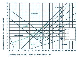
The Schaeffler diagram depicts the typical structure of steels after rapid cooling and the risk of potential defects that may occur when they are implemented (including grain growth, sigma phase formation, cold and hot cracks) as a function of their composition. The effects of austenite forming elements are expressed with nickel equivalents, and the effects of ferrite forming elements are expressed with chrome equivalents.

In this way we’re able to predict the diluted structure of the weld as a function of the specified filler metal and dissimilar metals that are welded together. Diagram 1 presents a classic example of how the diagram should be used. In the diagram, the weld’s structure is indicated with a red dot, and is considered advantageous for both welding and implementing corrosion resistant steels.

Diagram 1. The weld’s location on the Schaeffler diagram indicates a 20% material dilution when S235 unalloyed structural steel and 304L corrosion resistant steel is welded together using 309L filler metal.

At the same time, Diagram 1 also indicates that if the weld is prepared with an electrode  made for carbon steel, the red dot would fall directly into the martensitic zone. In this case, the weld would most likely crack due to its brittle structure.

General overview of nickel-based welding 3.

Nickel-based welding fillers can help compensate the stresses of brittle material arising from shrinkage during welding and their large deformation capacity. As a result, the brittle and difficult to weld material can be welded with nickel base consumable. Different iron and steel casting with high carbon content can be welded with nickel or ferronickel electrodes at a low heat input. Due to the brittleness of naturally lemezgrafitos steel castings at room temperature they can require a certain degree of preheating, but at a much lower temperature than if it was welded with with iron-based fillers. Gray, or malleable cast iron is welded with pure nickel-based electrodes with about 1% carbon content. In this case, the hardness of the weld seam is fairly low. Greater strength and hardness can be achieved by using ferro-nickel electrodes developed for the welding of cast irons and their various joints. Application of this electrode type results in small heat expansion, similar to that of invar alloy.

The heat expansion of unalloyed steel is 12×10-6/K, while that of 304/309 type austenitic stainless steel is 19×10-6/K. The large heat expansion difference at the border of welding seams in black and white joints can led to the development of great stresses as a function of changing temperature. The heat expansion of nickel is between that of carbon and stainless steel (15×10-6/K), which can result in smaller stresses at the border of the weld and the base material. When choosing a filler, all paired materials should be considered. Working conditions are also a very important factor when choosing filters. If a nickel base alloy is welded to a steel, then corresponding or similar Nickel fillers should be used.

The weld pool of nickel alloys is less liquid than unalloyed or even stainless steel. Otherwise, the viscosity of the weld pool and its dilution depends on the type of the alloy, that is, how much nickel is in the weld. In general, depending on what technology is used, a wider bevel and bigger root gap should be used when welding nickel alloys.

General overview of nickel-based welding 2.

Nickel, monel and nickel-molybdenum filler metals

Due to its protective oxide surface layer pure nickel is highly resistant to corrosion attacks even in highly chloridic environments. A typical base alloy is the Alloy 200 series, used for manufacturing chemical-, food- and power industry equipment. To weld the equipment, UTP 80 Ni and similar fillers have been developed (see Table 2.).  

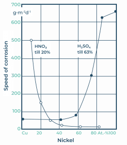
Pure nickel has a lower yield strength than general steels. Therefore pure nickel is not suitable for the manufacturing of structures working under relatively high stresses. Most alloying elements of nickel results in primarily solid solutions which has a strengthening effect. One of the alloying elements is copper, which can be completely dissolved in nickel. One example of this alloying system with a 30% copper addition to the nickel is MONEL. A representative example of this system is called the Alloy 400 series. Alloy 400 is typically used in so-called “offshore” applications, in systems working in  sea water or similarly salt heavy environments. The welding fillers developed for this purpose, and their typical chemical compositions, are shown in Table 2. Nickel-copper alloyed welding demonstrates outstanding corrosion resistance, not only in high concentrated NaOH alkali medium but also in slightly acidic environments (see figure 2.).

Figure 2. Speed of corrosion in nickel-copper alloy.

The R405 alloy is part of the Alloy 400 series, and contains a small amount of sulphur (0.025-0.060%) in order to ease machinability. Welding of R405 is difficult. The dilution of base material should be kept as low as possible during welding, in order to avoid the segregation of sulphur. If Alloy 400 is to operate in a hydrofluoric or calcium fluoride environment, a stress relieving heat treatment between 550-650 C should be applied after repair welding to prevent stress corrosion cracking.  

Different types of nickel-molybdenum alloys are similar to each other. Because of the molybdenum content, these materials have excellent corrosion resistance and especially high pitting corrosion resistance in chloridic, reductive environments. Previously, Alloy B types had to undergo a solid solution treatment at 1175 C after welding, due to the strong carbide precipitation in the heat affected zone, but the enhanced Alloy B-2 can be used in its welded condition. Because these alloys do not contain chromium, they have little resistant against oxidizing atmospheres. Alloy B-2 can be used in high temperatures in any concentration of hydrochloric acid. Depending on the welding process, either the UTP 703Kb basic electrode or UTP A 703 MIG wire or TIG rods are the most optimal.

Nickel-chromium-(cobalt-iron) alloyed fillers

Over the past 50 years, developments in the power plant industry, have resulted in built-in boilers, heat exchangers and turbines having to undergo three times more pressure and tension at up to 200-300 oC higher temperatures. This change led to the development of new materials and applications  within nuclear power plants, conventional power plants and waste energy power plants as well. The main advantage of nickel-chromium alloys is their maintained strength at higher temperatures and consistent resistance against the effects of oxidation due to its automatically generated oxide surface layer. The most well-known such alloy type is Alloy 600, which contains at least 15% chromium. Furnace walls and reactors built from these kinds of materials can be welded with UTP 068 HH or similar fillers, which are excellent in both oxidizing or carburizing environments. The further developed Alloy 690 contains with 29% chromium content. This material is typically applied in joint welding or pipe cladding in nuclear power plants. Alloy 690 exhibits outstanding resistance against intergranular stress corrosion cracking. While the base material tends to crack from heat, it can be welded securely with the correct technologies, like the UTP 6229Mn or the Thermanit 690 type filler.

Nickel-chromium, nickel-iron-chromium and nickel-chromium-molybdenum alloys are susceptible to carbide precipitation, but this has no considerable effect on its corrosion resistance, so it does not require a heat treatment solution after welding. In order to decrease carbide precipitation susceptibility, low carbon and stabilizing elements containing filler metals are used. After welding Alloy 600, if the equipment is working in a high temperature, alkali environment, a stress-relief annealing is carried out at 900 oC in order to avoid stress corrosion cracking.

There are a lot of carbide forming companion elements in nickel alloys. The carbides form chemical compounds in nickel-based alloys. The presence and distribution of carbides have an effect on the mechanical properties of the material and heighten its resistance against creep at higher temperatures. Precipitation hardenable nickel alloys are used to manufacture devices working under high mechanical stresses. These alloys must be exposed to heat treatment after welding. Depending on the alloy type, the heat treatment temperature is between 600-760 oC. If high strength is not required than another filler type can also be used.

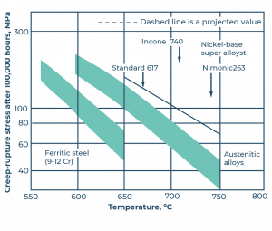
Alloy 617 is used as a base material for the pipes in conventional fossil-fueled boiler heat exchangers. As we can unequivocally establish from Figure 3, the creep limit of ferritic chromium steel is about 100 Mpa after 100,000 working hours at 600 oC, while Alloy 617 maintains a consistent creep strength, even at an elevated temperature of 700 oC.  

Figure 3. Creep fracture of different types of materials as a function of temperature after 100,000 working hours.


General overview of nickel-based welding 1.

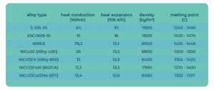
The occurrence of nickel is quite rare in the world. The raw ores are mined from sulphides-, oxides- or in silicate form. The metallic ore is enriched through further processing and nickel is subsequently produced by electrolysis or direct reduction. Pure nickel wire, sheets or piping processed using this method is widely used in many industries. Nevertheless, nickel is used in its pure state for manufacturing nickel alloys and surface coating, with steelmakers using the largest quantity of it in order to alloy steels. Within this field the application of nickel-based welding fillers is important. These are used with materials operating under heavily corrosive and/or hot working conditions, like cryogenic liquid gas tanks, the cladding of water turbines and . Nickel is also used for manufacturing equipment with dissimilar joints. Use of nickel-based welding materials is based on their physical and metallurgical properties. Table 1. shows the physical properties of different alloys.

Table 1. Some basic physical properties of nickel alloys. (alloy type, heat conduction, heat expansion, density, melting point)

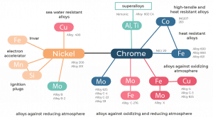
The main properties of different nickel alloys are: an austenitic structure, surface oxide layer, lack of allotropic transformation, and often also a precipitation-hardenable alloy. These properties specify the application fields of different alloys. Classification of nickel alloys according to alloying elements are shown in Figure 1.

Figure 1. Classification of nickel alloys according to their alloying elements

Among these alloying elements, copper is completely soluble in nickel, iron and chromium have a relatively good solubility, while molybdenum, cobalt, wolfram, vanadium, niobium and titanium are soluble to some extent in nickel as well. Welding filler manufacturers, including Böhler, have developed various kinds of welding materials for the different types of nickel alloy. Here we have introduced the fillers and examples of typical applications of them, in accordance with the classification of nickel alloys above. The data of the base materials and welding fillers mentioned in this article are demonstrated in Table 2.

Table 2. Data of typical nickel alloys and their welding fillers (number, nickel-based alloys/welding material, chemical composition, application, material number, EN name, ASTM name)


Dubai metro stations to use more than 25,000 tonnes of steel

Dubai’s metro and rail network is also continuously growing, reaching close to 50 stations the underground system connects various points and artificial islands in the desert city, raising myriad challenges for architects and construction crews alike.

While a number of the financial district’s metro stations are underground, much of the Red Line’s stations can be found looming over the 50km long, city-spanning Sheikh Zayed Road that in itself is two time 8 lanes wide at certain points. The steel structures of these stations is similarly impressive, connecting rails for over 80 self-driving trains capable of transporting up to 600 people each.

Curved roofs will be the signature of the metro stations, with an elevated shell-shape roofs intended to evoke the country’s pearl diving heritage. Generally, the stations are designed to be elliptical in shape, with the principle design philosophy being to wrap the station around the tracks.


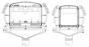
Air-conditioned, closed pedestrian bridges made up of modular elements lead up to the metro stations.


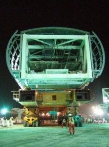
Before they are installed, each pedestrian bridge is fully assembled off-site, including the glazing, external cladding, internal fixtures and finishes, and electrical and mechanical infrastructure. The largest pedestrian bridge weighs well in excess of 200 tonnes.

Special self-propelled modular transporters transport the pedestrian bridges to the metro site and lift them onto piers. The piers have flared pier heads similar to those seen on the main viaduct structures of the metro.


Construction of the stations’ steel frameworks began after the Rail Agency erected the steel structures of every metro depot at the end of each line, where the trains will be parked and serviced. When construction is complete, nearly 5,000 tonnes of steelwork will have been used in the construction of the depots.

According to sources, construction of the Dubai metro project has exceeded 30B USD, a large part of which has Gond towards building, installing and welding the steel structures.

Sources:

http://www.amanaindustries.com/project/dubai-metro/

https://www.dubai-online.com/transport/metro/dubai-metro-red-line/

https://en.wikiarquitectura.com/building/dubai-metro/

https://www.emirates247.com/eb247/news/metro-stations-to-use-25-000-tonnes-of-steel-2008-01-11-1.216756

http://www.lusas.com/case/bridge/dubai_metro_footbridges.html